3.3.1. Survey and Locations File
The survey and locations file is used to predict synthetic field data (forward modeling). This file contains all necessary survey information including: the number of transmitters, transmitter geometry, observation locations and frequencies.
Note
Bolded entries are fixed flags recognized by the Fortran codes and blue hyperlinked entries are values/regular expressions specified by the user
The lines of the survey file are formatted as follows:
3.3.1.1. Parameter Descriptions
n_trx: The total number of unique transmitter-frequency pairs. Example: N_TRX 3
n_nodes: The number of nodes defining a particular transmitter loop. Note that:
xi yi zi: This refers to the X (Easting), Y (Northing) and Z (elevation) locations of the nodes defining the transmitter loop. Transmitters are defined using a right-handed coordinate system
fi: The frequency (in Hz) at which the subsequent set of measurements are made.
n_recv: The number of receivers collecting field observations at a particular frequency for a particular transmitter.
Loc Array: Contains the X (Easting), Y (Northing) and Z (elevation) locations for measurements at a particular frequency for a particular transmitter. It has dimensions n_recv \(\times\) 3.
3.3.1.2. Defining Transmitters
There are three types of transmitters that E3D survey files can use
3.3.1.2.1. Arbitrary source
Using this transmitter type, we can define both inductive sources (by closing the loop) or grounded sources (by not closing the loop). The Arbitrary Source is by far the most developed of the three source types. The ‘right-hand rule’ can be used to understand the relationship between the source current and the primary magnetic field it produces.
The block defining this transmitter type is given by:
where
TRX_LINES is a flag that must be entered
\(N\) is the number of nodes (# segments = N-1)
\(x_i, \; y_i, \; z_i\) are Easting, Northing and elevation locations for the nodes
3.3.1.2.2. Circular loop transmitter
This is an inductive source. The circular loop transmitter is defined using two lines:
where
TRX_LOOP is a flag that must be entered
\(x\) is the Easting, \(y\) is the Northing and \(z\) is the elevation location of the center of the loop
\(R\) is the radius of the loop
\(\theta\) is the azimuthal angle in degrees. A horizontal loop is defined by \(\theta = 0\)
\(\alpha\) is the clockwise angle from northing in degrees
3.3.1.2.3. Large inductive source
Here, we define the inductive source using a set of wire segments. When defining this type of transmitter, you must close the loop. The block defining this transmitter is given by:
where
TRX_ORIG is a flag that must be entered
\(N\) is the number of nodes (# segments = N-1)
\(x_i, \; y_i, \; z_i\) are Easting, Northing and elevation locations for the nodes
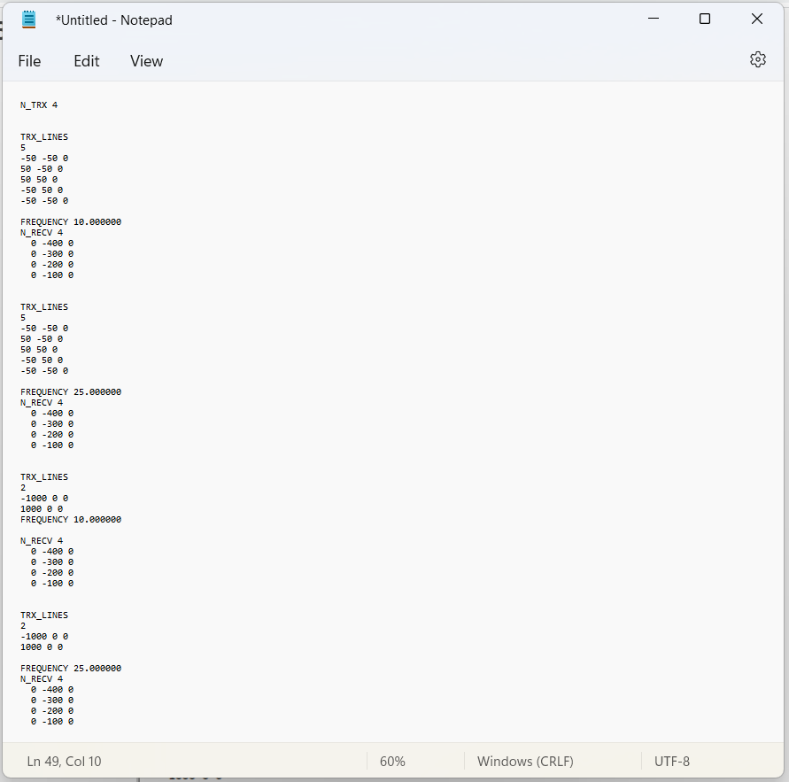
3.3.1.3. Example Survey File
Below, we show a survey file example. There is both an inductive and a galvanic source; each of which has 2 operating frequencies. Each source computes the fields at 4 locations. The path of the wire is defined according to the right-hand rule. The inductive source is a square loop defined in the counter-clockwise direction, resulting in a dipole moment pointing in the upward direction. The galvanic source is an electric dipole with positive current flowing from (-1000, 0, 0) to (1000, 0, 0). Therefore the primary magnetic field produced by the galvanic source at the Earth’s surface is up when standing North of the source, and down when standing South of the source.